Research

-
01. TF Conductor
Procurement completed
Total Value(kIUA)215.01
KO Allocation20.18%
KO Contribution(kIUA)43.39
-
02. Vacuum Vessel
Procurement completed
Total Value(kIUA)117.09
KO Allocation21.50%
KO Contribution(kIUA)25.20
-
03. Vacuum Vessel Ports
Total Value(kIUA)72.66
KO Allocation72.82%
KO Contribution(kIUA)52.91
-
04. Blanket Shield Block
Total Value(kIUA)56.34
KO Allocation49.82%
KO Contribution(kIUA)28.07
-
05. Assembly Tooling
Procurement completed
Total Value(kIUA)18.55
KO Allocation99.90%
KO Contribution(kIUA)18.53
-
06. Thermal Shields
Total Value(kIUA)26.56
KO Allocation100%
KO Contribution(kIUA)26.56
-
07. Tritium Storage & Delivery System(SDS)
Total Value(kIUA)12.50
KO Allocation94.25%
KO Contribution(kIUA)11.79
-
08. AC/DC Converters
Total Value(kIUA)113.56
KO Allocation40.14%
KO Contribution(kIUA)45.58
-
09. Diagnostics
Total Value(kIUA)204.89
KO Allocation1.93%
KO Contribution(kIUA)3.96
-
01. TF Conductor
![[TF Conductor] image](/kor/images/sub/a10205010100_01.jpg)
-
02. Vacuum Vessel
![[Vacuum Vessel] image](/kor/images/sub/a10205010100_02.jpg)
-
03. Vacuum Vessel Ports
![[Vacuum Vessel Ports] image](/kor/images/sub/a10205010100_03.jpg)
-
04. Blanket Shield Block
![[Blanket Shield Block] image](/kor/images/sub/a10205010100_04.jpg)
-
05. Assembly Tooling
![[Assembly Tooling] image](/kor/images/sub/a10205010100_05.jpg)
-
06. Thermal Shields
![[Thermal Shields] image](/kor/images/sub/a10205010100_06.jpg)
-
07. Tritium Storage & Delivery System(SDS)
![[Tritium Storage & Delivery System(SDS)] image](/kor/images/sub/a10205010100_07.jpg)
-
08. AC/DC Converters
![[AC/DC Converters] image](/kor/images/sub/a10205010100_08.jpg)
-
09. Diagnostics
![[Diagnostics] image](/kor/images/sub/a10205010100_09.jpg)
-
TF Conductor
What Is TF Conductor
TF magnet of tokamak is the primary part of tokamak reactor generating the toroidal field (the magnetic flux bundle in "doughnut-shape") which plays the main role to confine the plasma and maintain the equilibrium. The TF conductor will be wound into the magnet and carry the current of TF coils up to 68 kA in the superconducting state at the cryogenic condition.
Composition
Multi-Stage Superconducting Cable and Special 316LN Stainless Steel (316LN-IG-HT) Tube Superconducting Cable : Nb3Sn Superconducting Strands (900 wires), OFHC Srands (522 wires) and a Central Spiral Assembling 6 sub-cable of superconducting strands (150 wrie) and OFHC strands (87 wires) revolving around the central sprial as the axis of the last-stage cabling.
KO-DA's Responsibility for the Procurement
- 19 CICCs in 760m length, 8 CICCs in 415m length (※ total 18 TF magnets for ITER)
- 5 pieces of 760m CICC and 2 pieces of 415m CICC are necessary to construct one TF Magnet
- Cost : 43.39kIUA (total : 215.01kIUA)
※ Korea 20.18%, China 7.51%, Japan 14.99%, Russia 19.32%, U.S.A 7.82%, EU-Japan 10.00%
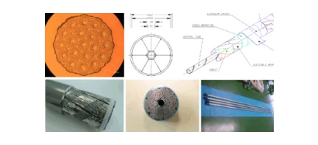
More about TF conductor
The following figure represents the CICC(Cable In Conduite Conductor) for ITER TF superconducting magnet. Being inside of a special 316LN stainless steal tube (316LN-IG-HT), this superconducting cable consists of central helium channel of metal spiral, which is to reduce a pressure drop of supercrtical He in the CICC, and 6 subcables surrounding the central channel, which is made of 150 superconducting strands and 87 pure copper wires twisted in multi-stage for cabling so that 900 superconducting and 522 copper strands are necessary for a cable.
To fabricate a piece of ITER TF magnet, 5 CICCs of 768m length and 2 CICCs of 428m length are required. Now, Korea is responsible for procuring 20% of the total CICC for ITER TF magnet, which is 19 CICCs of 768m and 8 CICCs of 428m. - 19 CICCs in 760m length, 8 CICCs in 415m length (※ total 18 TF magnets for ITER)
-
Vacuum Vessel
Function
- Generation and confinement of burning plasma for nuclear fusion
- Provide the ultra-high vacuum environment for plasma
- The first barrier of radioactivity materials like tritium
- Provide adequate radiation shielding for the magnets and reduce activation inside the cryostat
- Remove decay heat of all in-vessel components
- Support in-vessel components such as blanket, divertor, and etc.
Features
Size
- Torus OD : 19.4 m
- Torus height : 11.3 m
- Double wall thickness : 0.34-0.75 m
Surface area and volume
- Interior surface area : 850㎡
- Volume : 1,600 ㎥
Total weight : 5,124 ton
- Main vessel : 1,611 ton
- In-wall shield: 1,733 ton
- Port structures : 1,780 ton
KO procurement sharing
- Two 40 degree sectors (Weight : 400 ton, Height : 11.3 m, Width : 6.4 m)
- KO Contribution(klUA) : 25.20 klUA (Total Value(klUA) : 117.09 klUA)
※ Allocation : Korea 21.50%, EU 73.61%, IO 4.89%
Explanation
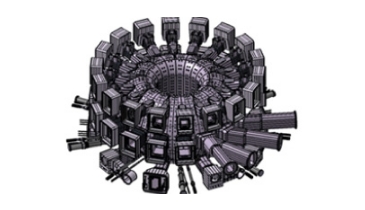
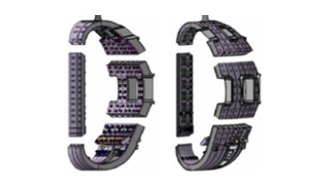
The main function of the ITER Vacuum Vessel (VV) main vessel is to provide a high vacuum for plasma and the primary confinement boundary. The vessel also supports the in-vessel component such as the blanket and the diverter. Also, the VV provides radiation shielding (the neutron heating is removed by the water circulating between the shells.
- The main vessel of torus-shaped double wall structure consists of 9 sectors of 40 degree and each sector which is delivered from the shop is assembled at site. Main material is stainless steel 316L(N)-IG of the ITER Grade.
- In-wall shield plate of SS 304B4 and SS 430 between shells is installed for neutron shielding during Tokamak operation.
- The outer diameter of the VV is 19.5 m and the height is 11.3m. Total weight after final assembly at site is about 5,000 tons.
- The VV is designed so that blankets can be attached to it and be cooled.
-
Vacuum Vessel Ports
Function
- ITER vacuum vessel port is parts of vacuum vessel component and coupling device of main vessel and cryostat.
Materials and components
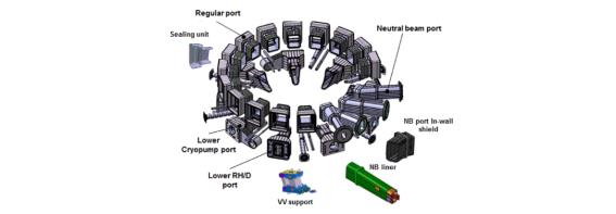
The main material of ports is stainless steel 316L(N)-IG of the ITER grade. Port structures are delivered to the ITER site and assembled between main vessel and cryostat after being fabricated and packaged as sub-item base.
Materials and components< Port item Period Upper Port - Upper Port (18 sets) Equatorial Port Regular Port (14 sets)
Heating Neutral Beam Port (3 sets)
Neutral Beam Duct Liner (3 sets)
Vacuum Sealing FlangesLower Port Remote Handling/Diagnositc Port (4 sets)
Cryopump Port (5 sets)
Local Penetration Ports
Vacuum Vessel Support (9 sets)Procurement Allocation
- All port items at equatorial and lower level (upper port: Russia)
- Total value of the items to be procured by Korea is 55.31 kIUA (Participate rate: 72.82 %)
- Participate rate of Russia : 27.18%
Detail
The port structures are used for equipment installation, utility feed-through, vacuum pumping and access inside the vessel for maintenance. Some port components are double wall construction with stiffening ribs between the shells and some components have a single wall construction. Normally, the VV ports consist of the port stub (that is integral to the main vessel), the stub extension and the port extension. The port extensions are equipped with the connecting ducts extended to the cryostat.
-
Blanket Shield Block
Function
- The blanket shield block provides the nuclear shielding of the vessel and external machine components. And, it has to remove the nuclear heating within the allowable temperature and stress limit.
Materials and components
- The blanket shield blocks consist of modules which are sufficiently small to be introduced and removed through the vessel equatorial ports, and light enough to be installed and transported by the blanket remote handling system.
- The configuration of blanket shield segmentation:
- 18 rows of modules are arrayed poloidally.
- The shield modules have a toroidal segmentation of 20° (18 modules) on the inboard and 10° (36 modules) on the outboard
- The inboard blanket shield block is 316L(N)-IG structure with 1.4 m toroidal length, 1 m poloidal length, and 0.4 m thickness. The inboard shield block has two poloidal recesses for the cooling manifolds that are located behind module. In the rear, there are also keyways, the cut-outs for the branch pipe and the seats for four flexible supports, a coaxial hydraulic connector and two electrical straps. Poloidal and toroidal cooling channels are machined in shield block to control flow paths and to enhance the heat exchange.
Item Contents Material 316L(N)-IG Total Number of Modules 440 modules Weight Limit per Module (including FW) 4.5 ton/module ![[KO procurement modules] image](/kor/images/sub/a10205010400_14.jpg) KO procurement modules
KO procurement modules
![[ITER blanket system(in-board module 01)] image](/kor/images/sub/a10205010400_15.jpg) ITER blanket system
ITER blanket system
(in-board module 01)![[Sectional view of in-board blanket shield block] image](/kor/images/sub/a10205010400_16.jpg) Sectional view of in-board
Sectional view of in-board
blanket shield blockProcurement Allocation
- KO agreed to procure the inboard blanket shields of #1, #2 and #6, #7, #8, #12, #13, #15, #16
- Procurement allocation : 49.82% (28.07 kIUA)
※ China : 50.18%
Core Technologies obtained from Blanket Shield Procurement
- Blanket shield should be designed and manufactured to satisfy the motivation by the desire to operate at high wall temperatures and at very high neutron-flux wall loading.
- Design and Analysis technologies
- Netronics Analysis
- Electromagnetic Analysis
- Thermo-hydraulic and Structural Analyses
- For the manufacturing of a shield block, the conventional fabrication technique based on drilling, milling and welding of forged SS blocks has been adopted. In addition, the powder HIP (Hot Isostatic Pressing) and the casting are being considered as alternative manufacturing methods. KO is considering the conventional way as fabrication method of blanket shield provisionally.
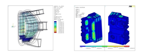 design and analysis for Blanket Shield Block
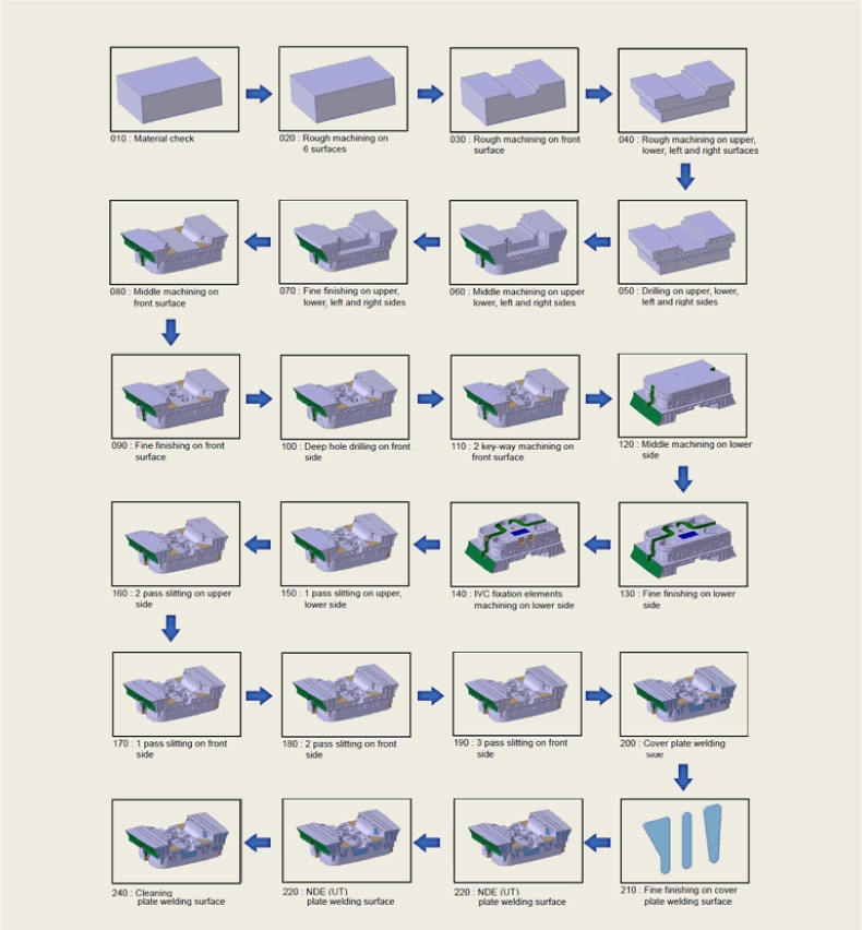 Manufacturing Procedure based on Convertional Techniques
-
Assembly Tooling
Component Description
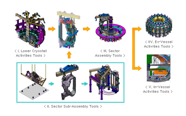
Procurement Allocation
- ITER Tokamak Assembly Tools are purpose-built tools to assemble the ITER tokamak components inside the cryostat.
- Measurement equipments, common lifting & standard tools are scope of ITER Organization.
- ITER Assembly tools are classified into 7 groups according to ITER Tokamak components.
- Sector Sub-Assembly Tools
- Sector Assembly Tools
- Cryostat Thermal Shield Assembly Tools
- PF Coil Assembly Tools
- Port & Piping Assembly Tools
- Central Solenoid Assembly Tools
- Correction Coil & Feeder Assembly Tools
- KO-DA supplies ITER Tokamak Assembly Tools and will carry out its design, fabrication, test, delivery, engineering support for site installation & test operation duties.
-
Thermal Shields
Function
- Minimize heat loads transferred by thermal radiation and conduction from warm components to superconducting magnets and structure that operate at 4.5 K.
- ITER thermal shield is cooled by pressurized helium gas with an 80 K inlet temperature. Temperature of the helium gas is maintained in the range of 80 ~ 100 K at normal operating state.
Composition
- The thermal shields consist of stainless steel 304L panels. The thermal shields are covered on both sides with a thin layer of silver with a minimum 5 μm thickness which ensures low emissivity less than 0.05.
-
Vacuum Vessel Thermal Shield (VVTS) : Inboard Section, Outboard Section
- Outboard section : 20 mm thickness, SS 304L panel
- Inboard section : 20 mm thickness, SS 304L panel
-
Cryostat Thermal Shield (CTS) : Upper CTS, Lower CTS, Equatorial CTS
- Upper CTS : Upper CTS Lid, Cylinder, five Shrouds
- Lower CTS : Lower CTS Floor, Cylinder
- Equatorial CTS : Connect to the VVTS
Component Description
- Credit : 26.56 kIUA (Total Credit:26.56 kIUA)
- KODA has 100% responsibility for ITER TS Procurement
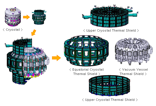
Detail
ITER thermal shield system minimizes heat loads transferred by thermal radiation and conduction from warm components to superconducting magnets and structure that operate at 4.5 K. The thermal shields consist of stainless steel 304L panels that are cooled by pressurized helium gas with an 80 K inlet temperature. Temperature of the helium gas is maintained in the range of 80 ~ 100 K at normal operating state. The thermal shields are covered on both sides with a thin layer of silver with a minimum 5 μm thickness which ensures low emissivity less than 0.05.
ITER Thermal Shields are comprised of vacuum vessel thermal shield (VVTS) and cryostat thermal shield (CTS). VVTS consists of inboard section and outboard section. CTS consists of upper CTS, lower CTS and equatorial CTS. Korea is responsible for the procurement of all ITER thermal shields-
Vacuum vessel thermal shield (VVTS)
- VVTS is made up of the single wall panel (20 mm thick). The circular cooling pipes are attached to the outer surface of the segments.
-
Cryostat thermal shield (CTS)
- Upper and Lower CTS are supported on the cryostat lid and cryostat floor, respectively, with the help of Ti-alloy supports. Upper CTS consists of upper CTS lid, upper CTS cylinder and five shrouds for the magnet feederline. Lower CTS consists of lower CTS floor and lower CTS cylinder. The equatorial CTS is structurally attached to the VVTS.
-
Tritium Storage & Delivery System(SDS)
Function
- Tritium Storage and Delivery System is a part of ITER fuel cycle, installed in the tritium plant. It stores and delivers the hydrogen isotopes and pure gases required for the ITER machine. SDS serves as a safe storage facility for the tritium and deuterium in the metal hydride form for the short-term operation and the long-term maintenance.
- Delivery of the hydrogen isotopes and pure gases
- Storage and delivery of tritium according to the ITER machine operation scenarios.
- Safe storage of tritium, inventory accountancy, and tritium tracking Operation of metal hydride bed for tritium
- Long-term storage of tritium and handling and accountancy facility for the imported tritium
Features and Components
- Composed of SDS(Storage and Delivery System) and TLS(Tritium Loading Station)
- Storage of the deuterium and tritium fuel gas (total tritium inventory less than 4 kg)
- Tritium inventory accountancy by measuring decaying heat
- Accurate tracking of tritium for the safety aspect
- Safe storage of tritium and deuterium using metal hybrid bed
- Systems installed in the glove boxes
- Buffer tank, gas line, valves and pumps must be tritium compatible
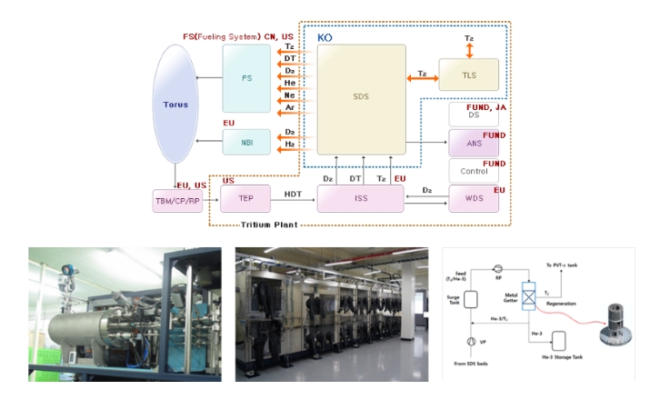
Detail
-
SDS(Storage and Delivery System)
- Metal hydride bed for deuterium and tritium storage and delivery : Hydrogen isotopes(deuterium and tritium) are stored in the form of metal hydride using DU.
- Glovebox : For the safe storage and operation of tritium gas, SDS system is installed in the glove box making at least double barrier for tritium.
- Buffer tank, pump, valves, gas lines, instrumentation : Buffer tank, pump, valves, gas lines, instrumentation should be tritium compatible.
- Pure gas(except tritium) delivery gas lines and instrumentation
-
TLS(Tritium Loading Station)
- Calorimetry : Trtium inventory measurement of tritium transport package
- Glovebox : For the safe storage and operation of tritium gas, TLS system is installed in the glove box making at least double barrier for tritium.
- Off-loading Furnace : Desorption of tritium from the transport package (metal hydride bed)
- Tritium gas transfer line and instrumentation
- Tritium Storage and Delivery System is a part of ITER fuel cycle, installed in the tritium plant. It stores and delivers the hydrogen isotopes and pure gases required for the ITER machine. SDS serves as a safe storage facility for the tritium and deuterium in the metal hydride form for the short-term operation and the long-term maintenance.
-
AC/DC Converters
Purpose
- The power needed to charge and stabilize the current in the TF (18) coils and to establish and control the current in the PF (6), CS (6), CCU/L+CCS (18) coils during the plasma pulse phases is provided by thyristor ac/dc converters.
- The breakdown and plasma initiation, the current drive and heating of the plasma, stabilization of the plasma vertical position are obtained by controlling the current profile in the coils.
Specifications
- Ac/dc converters have extremely high power, high current, high voltage ratings with maximum specifications of 78 MVA, 1,350 V, 68 kA respectively and total installation capacity is about 2GVA.
- Rectifier transformer, 12 pulse thyristor stack, inter-phase dc reactor are the main components in the total 44 units of ac/dc converters; TF (1), CS(12), VS1 (6), CC (9), PF (16). They are connected to the superconducting coils in series and/or parallel by DC busbar and disconnector switches.
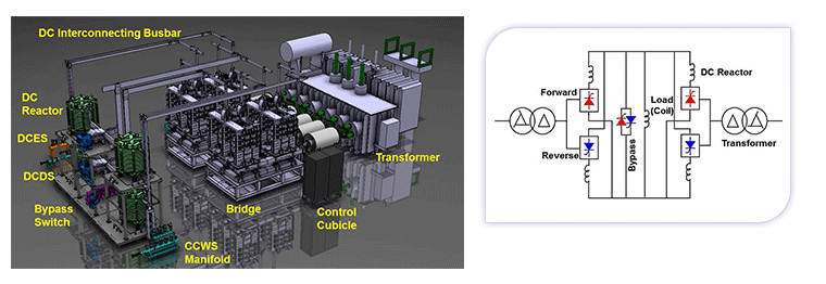 Main components of an ac/dc converter for ITER superconducting magnet
Procurement of KO-DA
- Procurement allocation: 45.58 kIUA (Total: 113.56 kIUA)
- Contribution rate: 40.14% (China 58.68%, IO 1.19%)
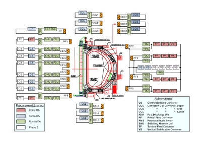 Configuration of ac/dc converters for ITER superconducting magnet
Specifications of ac/dc converters for ITER superconducting magnet
Specifications of ac/dc converters for ITER superconducting magnet Item Q'ty Ratings AC/DC Converter TF 1 68 kA, ±900 V CS 12 ±45 kA, ±1,350 V VS1 6 ±22.5 kA, ±1,350 V CC / CCU/L 6 ±10 kA, ±90 V CCS 3 ±10 kA, ±450 V PF 16 ±55 kA, ±1,350 V RPC & HF 3 750 Mvar, 66 kV Dummy Load 2 6.73 mH, 7.75 kA Functional Descriptions
- TF converter supplies continuous controlled current up to 68 kA to the TF coils for the long period of a few weeks/months of operation and is able to return power to grid, when necessary, from the energy up to 40 GJ stored in the coil.
- CS converters and PF converters provide controlled voltage and/or current for breakdown and plasma initiation. VS1 converters in the PF2-PF5 circuit provide fast current control to stabilize the plasma vertical position.
- CCU/L converters are mainly utilized to for the error magnetic field correction and CCS converters will make major contribution to stabilization of resistive wall modes (RWM).
- Reactive Power Compensators and Harmonic Filters (RPC&HF) limit the amount of reactive power the grid and the voltage distortion in the HV grid below the specified levels.
-
Diagnostics
KO-DA’s Responsibility for the Procurement
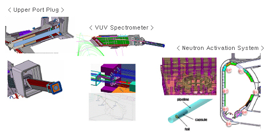 KO-DA’s Responsibility for the Procurement
Procurement Allocation
In order to control, optimize and evaluate long pulse plasma in ITER, it will be necessary to measure accurately and reliably a wide range of plasma parameters. Key parameters that describe the condition of the first wall and divertor will also have to be measured for machine protection. In total about 45 parameters will be measured. The measurements may be categorized into three groups according to their different roles in the ITER operational programme, as shown in Table 1.
1. those necessary for machine protection and basic plasma control;
2. those which can potentially be used for advanced plasma control;
3. additional measurements for evaluating the plasma performance and for understanding important physical phenomena which may limit ITER performance.Required Plasma and First Wall Measurements Grouped According to Operational Role
Specifications of ac/dc converters for ITER superconducting magnet GROUP la Measurements For Machine Protection and Basic Control GROUP lb Measurements for Advanced Control GROUP 2 Additional Measurements for Performance Eval, and Physics - Plasma shape and position, separatrix-vall gaps, gap between seqaratrixes
- Plasma current, q(a), q(95%)
- Loop voltage
- Fusion power
- BN=Btor(aB/I)
- Line-averaged electron density
- Impurity and D,T influx(divertor, & main Plasma)
- Surface temp.(div. & upper plates)
- Surface temperature(first wall)
- Runaway electrons
- 'Halo'currents
- Radiated power(main pla, X-pt & div)
- Divertor detachm ent indicator(Jsat,ne,Teat divertor plate)
- Disruption precursors (locked modes,m=2)
- H/L mode indicator
- Zeff(line-averaged)
- nT/nD in plasma core
- ELMs
- Gas pressure(divertor & duct)
- Gas composition(divertor & duct)
- Dust
- Neutron and α-source profile
- Helium density profile(core)
- Plasma rot.(tor and pol)
- Current density profile(q-profile)
- Electron temperature profile(core)
- Electron den profile(Core and edge)
- Ion temperature profile(core)
- Radiation power profile(core, X-point & divertor)
- Zeffprofile
- Helium density(divertor)
- Heat deposition profile(divertor)
- Ionization front position in divertor
- Impurity density profiles
- Neutral density between plasma and first wall ne of divertor plasma
- Te of divertor plasma
- Alpha-paricle loss
- Low m/n MHD activity
- Sawteeth
- Neterosion(divertor plate)
- Neutron fluence
- Confined α-particles
- TAE Modes, fishbones
- Te profile(edge)
- ne, Te profiles(X-point)
- Ti in divertor
- Plasma flow(divertor)
- nT/nD/nH(edge)
- nT/nD/nH(divertor)
- Te fluctuations
- ne fluctuations
- Radial electric field and field fluctuations
- Edge tur bulence
- MHD activity in plasma core
The measurements will be made with an extensive diagnostic system comprising about 40 individual measurement systems, which can be categorized according to applied measurement methods: magnetic diagnostics, neutron diagnostics, optical diagnostics, spectroscopic and NPA(Neutral Particle Analyser), microwave diagnostics. Each diagnostic system can be divided largely into 4 parts: signal receiving part from plasma, signal transmission part, signal measurement part, and data acquisition & analysis part. These diagnostic systems are installed all over the tokamak building, starting from the vacuum vessel to the diagnostic room, as shown in Fig. 1. Especially the signal receiving part of the diagnostics is installed in four locations - within the vacuum vessel, in divertor ports, and in equatorial and upper ports, taking into account measurement requirements, shielding, vacuum boundaries and activation requirements, length and complexity of transmission lines, and maintenance requirements as well as requirements for confinement of radioactive materials.
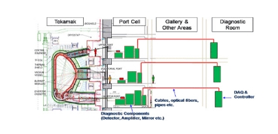 ITER Diagnostic System Installation Layout
Procurement for the ITER diagnostic system is allocated among the seven participants according to the port-based standards and the participation ratio. The procurement allocation was based mainly on the port-based diagnostic packages. ITER diagnostics have 32 procurement packages in total. Each port-based package consists of one port plug, one lead diagnostic, and other diagnostic systems assigned to the same port. KO-DA will procure one diagnostic upper port plug and two diagnostic systems including the VUV spectrometer and the neutron activation system, which corresponds to 3.5% of total ITER diagnostic credit.
-
Diagnostic Upper Port Plug (WBS 55 N.03)
The ITER diagnostic port plug is a supporting structure of diagnostic components installed within the vacuum vessel. It is fixed to the vacuum vessel port as a cantilevered beam with bolts. The intrinsic function of the port plug is to support and protect diagnostics components, such as mirrors, waveguides, shutters and so on, from high temperature plasma (~10keV) and fast neutrons (14MeV). Besides the inherent role, it forms a primary vacuum boundary, and provides neutron shielding to protect the surrounding systems like superconducting magnets. ITER has 18 port plugs in the upper and equatorial port, respectively. Among them, 12 upper ports and 6 equatorial ports are used for diagnostic systems installation. The KO-DA will provide one upper port plug which is installed in the upper port No. 18. The upper port plug has a constructive configuration of approximately 6m x 1m x 1m size and more than 20 tons, integrating diagnostic shielding modules inside. Diagnostic systems installed in the upper port plug 18 are the VUV spectrometer and the neutron activation system, which are all in KO-DA procurement package.
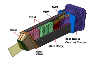 ITER Diagnostic Upper Port Plug No.18
-
VUV Spectrometer (WBS 55 E.03)
The VUV spectrometer measures radiation from ionized impurities from the plasma edge in the range of 21-26 nm and core in the range of 2.3-160 nm. The monitoring of these impurity species will be important for monitoring of the overall machine conditions, real time control of the impurity level and for diagnosis of impending fault conditions. The KO DA will procure three VUV spectrometers (one imaging, one survey, and one divertor) that will be installed at Upper Port 18, and Equatorial Port 11 (and/or Divertor Port), respectively. The upper system is designed as a VUV imaging spectrometer with one cylindrical mirror and one toroidally focusing collimating mirror, and a flat-field 2D imaging spectrograph with MCP/CCD detector. The design of the equatorial system employs a VUV survey spectrometer with multi channels for wide-range coverage of the VUV/XUV spectrum. The VUV survey spectrometer is designed as 5-channel system by dividing the wavelength range, so that the high resolution of spectral lines and the real time data acquisition could be realized. The divertor VUV spectrometer is under conceptual design.
-
Neutron Activation Systems (WBS 55 B.08)
14 MeV neutrons are generated as a result of a D-T fusion reaction of ITER plasma. A neutron activation system evaluates the neutron fluence on the first wall and the total fusion power by measuring neutrons near the first wall. This system measures gamma rays from the metal samples which are activated by the neutron flux, and the samples are transferred between the irradiation end and the counting station by the pneumatic method.
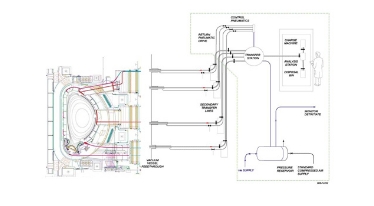 ITER Neutron Actication System Layout

보안문자를 입력 후 확인 버튼을 누르세요.
